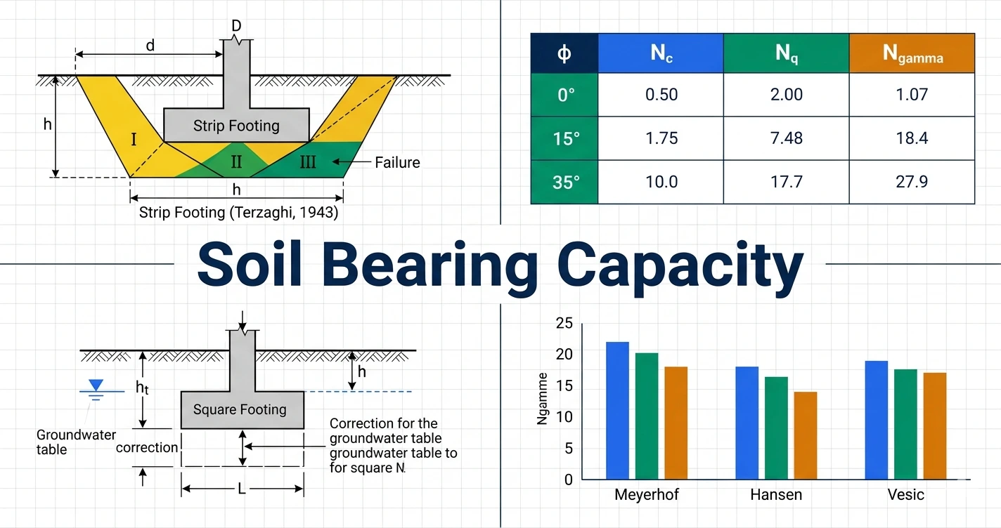
Key Numbers: Why Bearing Capacity Matters
Four quick visual snapshots before diving in — typical allowable pressures by soil type, the dramatic effect of groundwater, how phi drives all BC factors, and why settlement usually governs over shear.
Bearing Capacity: Every Term Precisely Defined
Soil bearing capacity is the ability of soil to safely carry the loads transferred to it from a foundation without shear failure of the soil mass or excessive settlement of the structure. It is expressed as pressure (kPa, kN/m², or tsf). Two criteria must always be checked independently: (1) shear failure, and (2) settlement. The more critical governs the final footing size.
Three Shear Failure Modes: Theory, Diagrams & Criteria
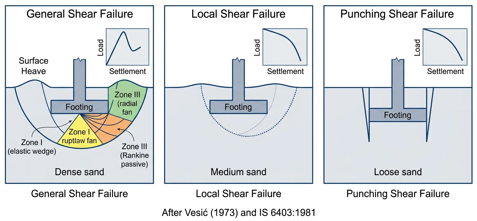
General Shear Failure
Dense/stiff soils (Dr > 67%, stiff clay). Continuous failure surface to ground; sharp load-settlement peak; heave on both sides. Terzaghi formula applies directly.
Local Shear Failure
Medium soils (Dr 35–67%). Failure zone does not reach surface. Large settlement before failure; slight heave. Use reduced c* = 0.67c, tan(φ*) = 0.67tanφ in Terzaghi.
Punching Shear Failure
Very loose/soft soils (Dr < 35%) or deep footings. No defined failure surface; footing punches down; no heave. Vesic/Meyerhof depth factors correct for this.
| Failure Mode | Soil Condition | SPT N (sand) | Dr (sand) | Load-Settlement Curve | Surface Heave | Formula Applicability |
|---|---|---|---|---|---|---|
| General Shear | Dense sand, stiff clay | >30 | >67% | Sharp peak, sudden drop | Pronounced both sides | Terzaghi, Meyerhof, Hansen, Vesic directly |
| Local Shear | Medium dense sand, medium clay | 10–30 | 35–67% | Gradual; no clear peak | Slight | Terzaghi: c* = 0.67c; φ* = arctan(0.67tanφ) |
| Punching Shear | Loose sand, soft clay; deep footings | <10 | <35% | Continuous settlement; no peak | None | Meyerhof/Vesic depth and compressibility factors |
Factors Affecting Soil Bearing Capacity
| Factor | Symbol | Effect on qu | Quantitative Impact | Design Note |
|---|---|---|---|---|
| Cohesion | c (kPa) | Direct proportional: c·Nc term | Each +1 kPa cohesion adds Nc kPa; e.g. at φ=30°, Nc=30: each +1 kPa c adds 30 kPa to qu | Undrained φ=0: qu = 5.14cu (strip). Measure cu from UU triaxial or vane shear |
| Friction angle | φ (degrees) | Exponential via Nq and Nγ | φ: 30° to 35° doubles Nq; nearly triples Nγ | Use drained φ' for long-term; undrained φu=0 for short-term saturated clay |
| Unit weight | γ (kN/m³) | Affects overburden q and Nγ·B term | Above GWT: 18–21; below GWT: buoyant γ' ≈ 8–11 kN/m³ | Use γ' below groundwater table in both q and γ·B terms |
| Foundation depth | Df (m) | Increases overburden q = γ×Df; Nq term grows | Doubling Df roughly doubles q term contribution to qu | Min. Df per IS 1080: 0.5 to 1.0 m; deeper = higher capacity but higher cost |
| Foundation width | B (m) | Increases Nγ×B term; for clay (φ=0): no effect | Sand: wider footing has higher qu. Clay: qu independent of B | Clay: increasing B improves settlement capacity; does not change unit bearing capacity |
| Footing shape | B/L | Shape factors sc, sq, sγ modify each term | Square vs strip: sc increases from 1.0 to 1.3; sγ decreases from 1.0 to 0.8 | Always apply shape factors for non-strip footings |
| Groundwater table | dw (m) | Reduces effective unit weight below GWT | GWT at footing level: qu reduced 35–55% for typical sand vs deep GWT | Three correction cases based on GWT position relative to Df and B |
| Load inclination | α (deg) | Inclination factors ic, iq, iγ reduce qu | α=20°: capacity reduced 30–60% depending on soil | Apply for wind, seismic, earth pressure on basement walls |
| Ground slope | β (deg) | Ground inclination factors gc, gq, gγ (Hansen) | 10° slope: reduces qu 15–30% | Footings on embankments or near excavations |
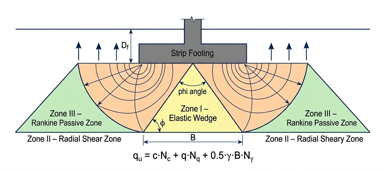
Terzaghi's Bearing Capacity Theory: Full Equations, Factors & Mechanism
Karl Terzaghi (1943) was the first to propose a rigorous analytical method for the ultimate bearing capacity of a shallow footing. His assumptions: (1) general shear failure; (2) soil above the foundation base acts as a surcharge only ($q = \gamma D_f$, not as soil with shear strength); (3) rough footing base; (4) failure mechanism has three zones: Zone I (elastic wedge at angle φ beneath footing), Zone II (radial shear zone, logarithmic spiral boundary), Zone III (Rankine passive zone). The condition Df ≤ B defines a shallow footing in Terzaghi's original framework.
| φ (°) | Nc (Terzaghi) | Nq | Nγ (approx.) | Soil Description |
|---|---|---|---|---|
| 0 | 5.7 | 1 | 0 | Saturated clay, undrained (φ=0) |
| 5 | 7.34 | 1.57 | 0.07 | Soft clay |
| 10 | 9.61 | 2.47 | 0.37 | Firm clay |
| 15 | 12.86 | 3.94 | 1.1 | Medium clay |
| 20 | 17.69 | 6.4 | 2.87 | Stiff clay / very loose sand |
| 25 | 25.13 | 10.66 | 6.77 | Loose to medium sand |
| 28 | 31.61 | 14.72 | 11.19 | Medium sand |
| 30 | 37.16 | 18.4 | 15.1 | Medium-dense sand |
| 32 | 44.04 | 23.18 | 20.79 | Dense sand |
| 35 | 57.75 | 33.3 | 33.92 | Very dense sand / dense gravel |
| 38 | 73.03 | 48.93 | 52.19 | Dense gravel |
| 40 | 95.67 | 64.2 | 73.4 | Very dense gravel |
| 45 | 172.29 | 134.87 | 192 | Rock-like dense gravel |
Meyerhof's Theory: Shape, Depth & Inclination Factors
G.G. Meyerhof (1951, 1963) extended Terzaghi's formula by rigorously incorporating shape factors, depth factors, and inclination factors into a unified general equation. His $N_q$ and $N_c$ are derived analytically from the Prandtl logarithmic spiral mechanism and are considered more accurate than Terzaghi's. Meyerhof's method is the basis for most North American practice (FHWA GEC No.6, AASHTO). A key innovation: Meyerhof extended the failure surface above the footing base, accounting for the shear strength of soil above footing level — which Terzaghi ignored.
| Shape Factors (Meyerhof) | Depth Factors (k = Df/B) | Inclination Factors | ||||||
|---|---|---|---|---|---|---|---|---|
| Factor | φ = 0 | φ > 10° | Factor | φ = 0 | φ > 10° | Factor | Expression | Notes |
| sc | 1 + 0.2 B/L | 1 + 0.2(B/L)Nφ | dc | 1 + 0.2(Df/B) | 1 + 0.2k√Nφ | ic | (1 − α/90)² | α = load inclination from vertical (deg) |
| sq | 1.0 | 1 + 0.1(B/L)Nφ | dq | 1.0 | 1 + 0.1k√Nφ | iq | (1 − α/90)² | Same as ic for φ > 0 |
| sγ | 1.0 | 1 + 0.1(B/L)Nφ | dγ | 1.0 | 1 + 0.1k√Nφ | iγ | (1 − α/φ)² | iγ = 0 when α ≥ φ |
| Nφ = tan²(45 + φ/2). For square/circle: B/L = 1. For strip: B/L = 0 (all shape factors = 1.0). | ||||||||
Hansen's Method: Full Factor Set Including Base & Ground Slope
J. Brinch Hansen (1970) published the most comprehensive bearing capacity formulation. Beyond Meyerhof's factors, he added base inclination factors ($b_c$, $b_q$, $b_\gamma$) for tilted footing bases, and ground inclination factors ($g_c$, $g_q$, $g_\gamma$) for footings on sloping ground. Hansen's depth factors differ from Meyerhof's and are more accurate for deep footings (Df/B > 1). Hansen's method is the basis of Eurocode 7 Annex D and British Standard BS 8004.
| Factor Group | Factor | Expression | Notes / Conditions |
|---|---|---|---|
| Shape | sc | 1 + (Nq/Nc)(B/L) for φ>0; 1 + 0.2 B/L for φ=0 | Square: B/L=1; strip: B/L=0 |
| sq | 1 + (B/L)tanφ | φ > 0 only | |
| sγ | 1 − 0.4(B/L) | Minimum 0.6; strip: 1.0 | |
| Depth (k = Df/B if ≤1; k = arctan(Df/B) rad if >1) | dc | 1 + 0.4k for φ>0; 1 + 0.4arctan(Df/B) for φ=0 | More accurate than Meyerhof for deep footings |
| dq | 1 + 2tanφ(1−sinφ)² k | Same k definition | |
| dγ | 1.0 (always) | Hansen sets depth factor for γ term to 1.0 | |
| Inclination (QH = horiz. load; m = (2+B/L)/(1+B/L)) | ic | iq − (1−iq)/(Nq−1) for φ>0; 1 − m·QH/(A·c·Nc) for φ=0 | Must satisfy QH < QVtanφ + cA |
| iq | (1 − QH/(QV + Ac·cotφ))m | Use mB or mL depending on load direction | |
| iγ | (1 − QH/(QV + Ac·cotφ))m+1 | = 0 when φ = 0 | |
| Base inclination (ψ = base tilt from horizontal, radians) | bc | 1 − 2ψ/(2+π) for φ>0; 1 − ψ/147° for φ=0 | ψ in radians in formula |
| bq = bγ | (1 − ψ·tanφ)² | Positive ψ tilts toward direction of horizontal load | |
| Ground slope (β = slope angle from horizontal, radians) | gc | 1 − 2β/(2+π) for φ>0; 1 − β/147° for φ=0 | For footing on inclined ground surface |
| gq = gγ | (1 − tanβ)² | β in radians in formula |
Vesic's Method: Revised Nγ and Soil Compressibility Correction
A.S. Vesic (1973, 1975) refined Hansen's framework by revising $N_\gamma$ and introducing a soil compressibility correction factor ($I_{rc}$) for loose or soft soils where local/punching shear governs. Vesic's shape factors closely follow Hansen's. His method is widely used in US practice (AASHTO LRFD, FHWA).
| φ (°) | Nc (all theories) | Nq (all) | Nγ Hansen | Nγ Vesic | Nγ Meyerhof |
|---|---|---|---|---|---|
| 0 | 5.14 | 1 | 0 | 0 | 0 |
| 5 | 6.49 | 1.57 | 0.09 | 0.45 | 0.07 |
| 10 | 8.35 | 2.47 | 0.47 | 1.22 | 0.37 |
| 15 | 10.98 | 3.94 | 1.42 | 2.49 | 1.1 |
| 20 | 14.83 | 6.4 | 3.54 | 3.64 | 2.87 |
| 25 | 20.72 | 10.66 | 8.11 | 6.77 | 6.77 |
| 30 | 30.14 | 18.4 | 15.07 | 22.4 | 15.67 |
| 35 | 46.12 | 33.3 | 33.92 | 48.03 | 33.92 |
| 40 | 75.31 | 64.2 | 79.54 | 109.41 | 73.4 |
| 45 | 133.88 | 134.87 | 200.81 | 271.76 | 192 |
Groundwater Table Correction: Three Cases Fully Explained
The groundwater table (GWT) reduces the effective unit weight of saturated soil below it to the buoyant value: $\gamma' = \gamma_{sat} - \gamma_w \approx 8$–$11\;\text{kN/m}^3$ (roughly half of moist unit weight). This affects two separate terms in the bearing capacity equation: the overburden term $q = \gamma D_f$ and the self-weight term $\frac{1}{2}\gamma B N_\gamma$. Three cases are defined by depth of GWT relative to $D_f$ and footing width $B$.
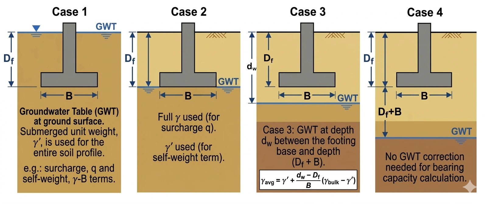
| Case | GWT Location | Overburden term q = γDf | Self-weight term ½γBNγ |
|---|---|---|---|
| Case 1 | GWT at or above ground surface (dw = 0) | Use γ' throughout: q = γ' × Df | Use γ' in place of γ |
| Case 2 | GWT exactly at footing base (dw = Df) | No change: q = γ × Df (γ above GWT is full) | Use γ' in place of γ |
| Case 3 | GWT within B below footing base (Df < dw < Df + B) | No change: q = γ × Df | Use interpolated γ̄ (see formula below) |
| Case 4 | GWT deeper than Df + B below surface | No change | No change; GWT has no effect on qu |
Quantitative impact example: For a 2.0 m square footing at Df = 1.5 m in medium dense sand (φ = 32°, γ = 19 kN/m³, γ' = 9.5 kN/m³): GWT well below (Case 4): qu ≈ 1,380 kPa. GWT at foundation level (Case 2): qu ≈ 980 kPa. GWT at ground surface (Case 1): qu ≈ 620 kPa. GWT can reduce qu by 35–55%. Always determine GWT during site investigation and recheck seasonally if GWT fluctuates.
Special Cases: Saturated Clay, Eccentric Load, Two-Layer Soil
Field Determination: SPT, CPT and Plate Load Test
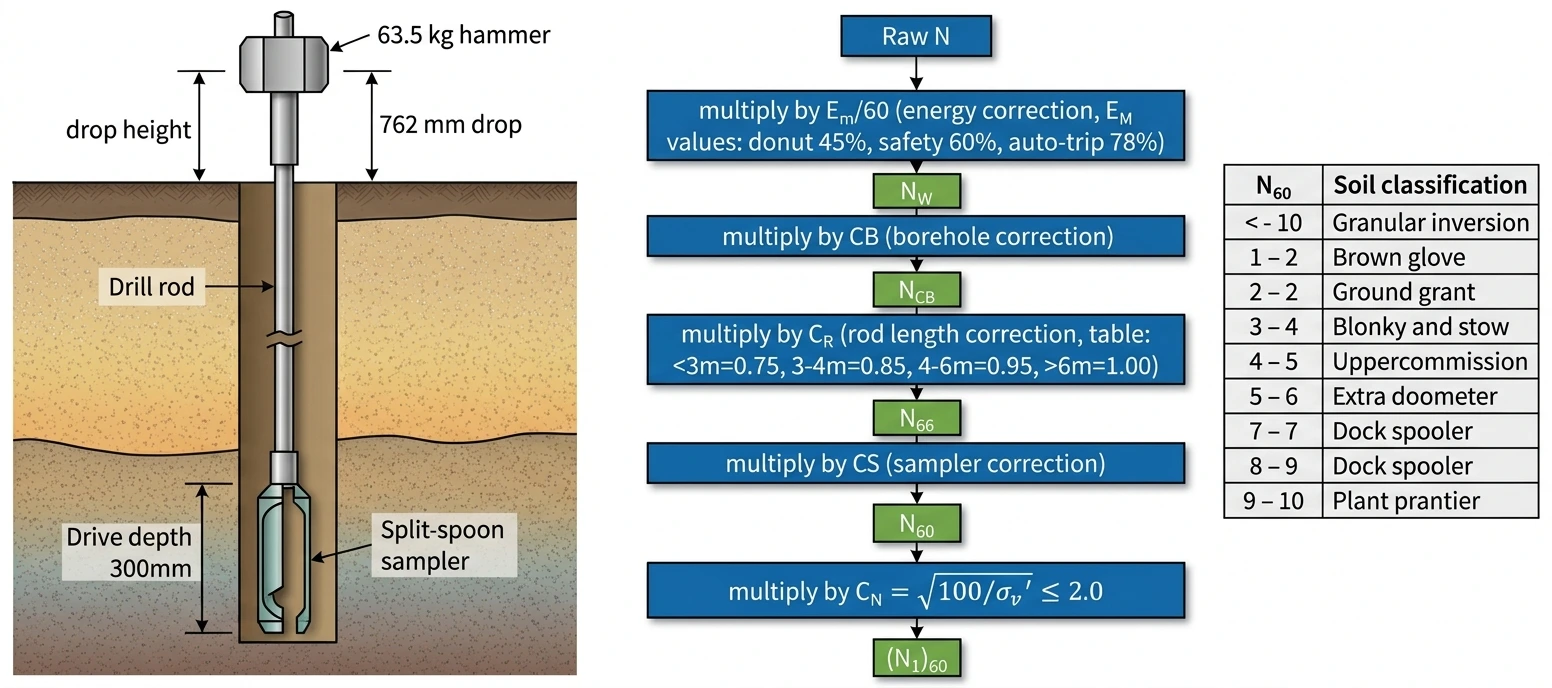
Standard Penetration Test (SPT)
The SPT (ASTM D1586 / IS 2131) is the most widely used in-situ test worldwide. A 51 mm split-spoon sampler is driven 450 mm into the borehole by a 63.5 kg hammer falling 762 mm; the blow count for the last 300 mm is recorded as the raw N-value. Raw N is corrected to $N_{60}$ (standardised to 60% energy) and then $(N_1)_{60}$ (overburden-corrected to 100 kPa reference) before use in correlations.
| N60 | Sand Classification | φ' estimate | qa for 25 mm settlement (kPa) | Clay Classification | cu estimate (kPa) |
|---|---|---|---|---|---|
| 0–4 | Very loose | 25–28° | 0–50 | Very soft | 0–25 |
| 5–10 | Loose | 28–30° | 50–100 | Soft | 25–50 |
| 11–20 | Medium dense | 30–35° | 100–200 | Medium stiff | 50–100 |
| 21–30 | Dense | 35–40° | 200–300 | Stiff | 100–200 |
| 31–50 | Very dense | 38–43° | 300–500 | Very stiff | 200–400 |
| >50 | Rock-like / cemented | >43° | >500 | Hard | >400 |
Cone Penetration Test (CPT)
The CPT (ASTM D3441 / IS 4968 Part III) pushes a 10 cm² cone at 20 mm/s and continuously measures tip resistance $q_c$ (MPa), sleeve friction $f_s$ (kPa), and pore pressure $u_2$ (kPa). The friction ratio $F_r = f_s/q_c \times 100\%$ is used for soil classification. CPT gives a continuous profile without sampling disturbance.
Plate Load Test (PLT)
The PLT (IS 1888 / ASTM D1194) places a rigid steel plate (typically 300–600 mm square) at the proposed foundation level and applies incremental loads while measuring settlement. A load-settlement curve is plotted; $q_u$ from the plate is defined at the intersection of two tangents drawn to the bilinear curve.
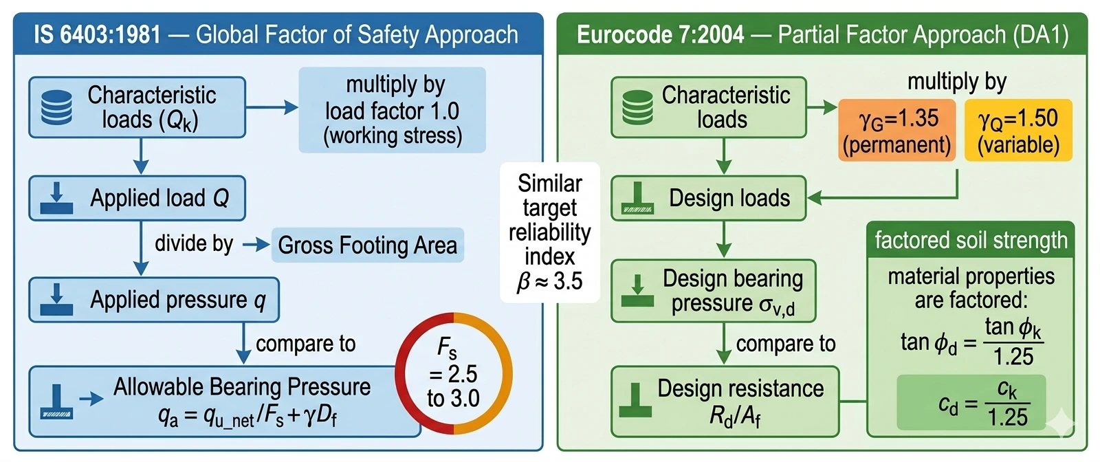
IS 6403, AASHTO, Eurocode 7: Requirements and FoS
| Standard | Country | Recommended Theory | FoS (Shear) | Settlement Limit (isolated) | Key Distinguishing Feature |
|---|---|---|---|---|---|
| IS 6403:1981 | India | Terzaghi for simple cases; Hansen for inclined/eccentric | 2.5–3.0 (net qu) | 25 mm sand; 40 mm clay (IS 1904) | Specific GWT correction rules; presumptive BC table; widely used in Indian practice |
| IS 1904:1986 | India | Settlement criteria companion to IS 6403 | Referenced from IS 6403 | 25/40/65 mm (sand/clay/raft); diff.: 18–25 mm | Governs most Indian foundation design; differential settlement limits are critical |
| FHWA GEC No. 6 (2006) | USA | Meyerhof shape/depth; Vesic Nγ | 2.5–3.5 (net qu) | 25–50 mm | Standard US reference for shallow foundations; detailed factor tables |
| AASHTO LRFD 9th Ed. | USA (bridges) | Meyerhof/Vesic; LRFD resistance factors | φbc = 0.50 (equiv. FoS ≈2.0–2.5) | Structure-specific; typically 25 mm | Load and Resistance Factor Design; separate factors per limit state |
| Eurocode 7 (EN 1997-1:2004) | Europe | Hansen (Annex D); Design Approaches 1, 2, or 3 | Partial factors: γc = 1.25 (GEO) | S4 performance class; structure-specific | Partial material and load factors; three Design Approaches per National Annex |
| BS 8004:2015 | UK | Hansen; references EC7 DA1 | EC7 partial factors | 25–50 mm guidance | Supersedes BS 8004:1986 presumptive BC tables; aligned with EC7 |
| NBC 105:2020 | Nepal | IS 6403 methods + NBC seismic load combinations | 2.5–3.0 | Per IS 1904 | Seismic zone factor reduces allowable BC; NBC seismic provisions mandatory |
IS 6403 presumptive bearing capacity values (Table 1) for preliminary design only: Soft/medium clay 50–100 kPa. Stiff clay 100–200 kPa. Hard clay 200–400 kPa. Loose sand 100 kPa. Medium sand 100–200 kPa. Dense sand 200–400 kPa. Gravel 400–600 kPa. Weathered rock 600–2,000 kPa. These are gross allowable pressures. Never use for final design of any structure requiring a proper geotechnical investigation.
Complete Worked Example: Square Footing by Meyerhof (IS 6403)
Problem: A 2.0 m × 2.0 m square footing is to be placed at $D_f = 1.5$ m in medium dense sandy soil. Soil: $c = 0$, $\phi = 30°$, $\gamma = 18$ kN/m³, $\gamma_{sat} = 19.5$ kN/m³. The groundwater table is at 3.0 m below ground surface (1.5 m below footing base; $B = 2.0$ m: Case 3 GWT correction). Vertical central load only. Required: (1) $q_u$ by Meyerhof; (2) $q_{nu}$; (3) $q_a$ with $F_s = 3.0$; (4) allowable column load.
Step-by-Step Solution
Settlement Criteria and Calculation Methods
Total foundation settlement = Immediate (elastic) settlement $S_i$ + Primary consolidation $S_c$ + Secondary compression $S_s$. For sands and gravels, $S_i$ dominates (drainage is fast; $S_c$ and $S_s$ negligible). For soft to medium clays, $S_c$ dominates and may continue for years to decades.
| Foundation Type | Soil | Max. Total Settlement | Max. Differential Settlement | Standard |
|---|---|---|---|---|
| Isolated footing | Sand and gravel | 25 mm | 18 mm | IS 1904; IS 6403; FHWA |
| Isolated footing | Clay | 40 mm (up to 65 mm with caution) | 25 mm | IS 1904 |
| Raft foundation | Sand | 50 mm | 25 mm | IS 1904 |
| Raft foundation | Clay | 65–100 mm | 40–65 mm | IS 1904 |
| Frame structure | Any | 25–50 mm | L/500 (angular distortion) | Eurocode 7; AASHTO |
| Sensitive machinery | Any | 5–10 mm | 2–5 mm | Project-specific |
Why settlement often governs over shear: For most practical footings on loose sand or clay, the allowable bearing pressure derived from settlement limits (25 mm on sand, 40 mm on clay) is typically 100–200 kPa, which is well below the safe bearing capacity from shear analysis (often 300–600 kPa). This means the footing must be sized to keep contact pressure below 100–200 kPa, not the 300–600 kPa the soil could resist in shear. Always check both criteria and use the lower governing value.
Charts: Bearing Capacity Factors, GWT Impact & SPT Correlations
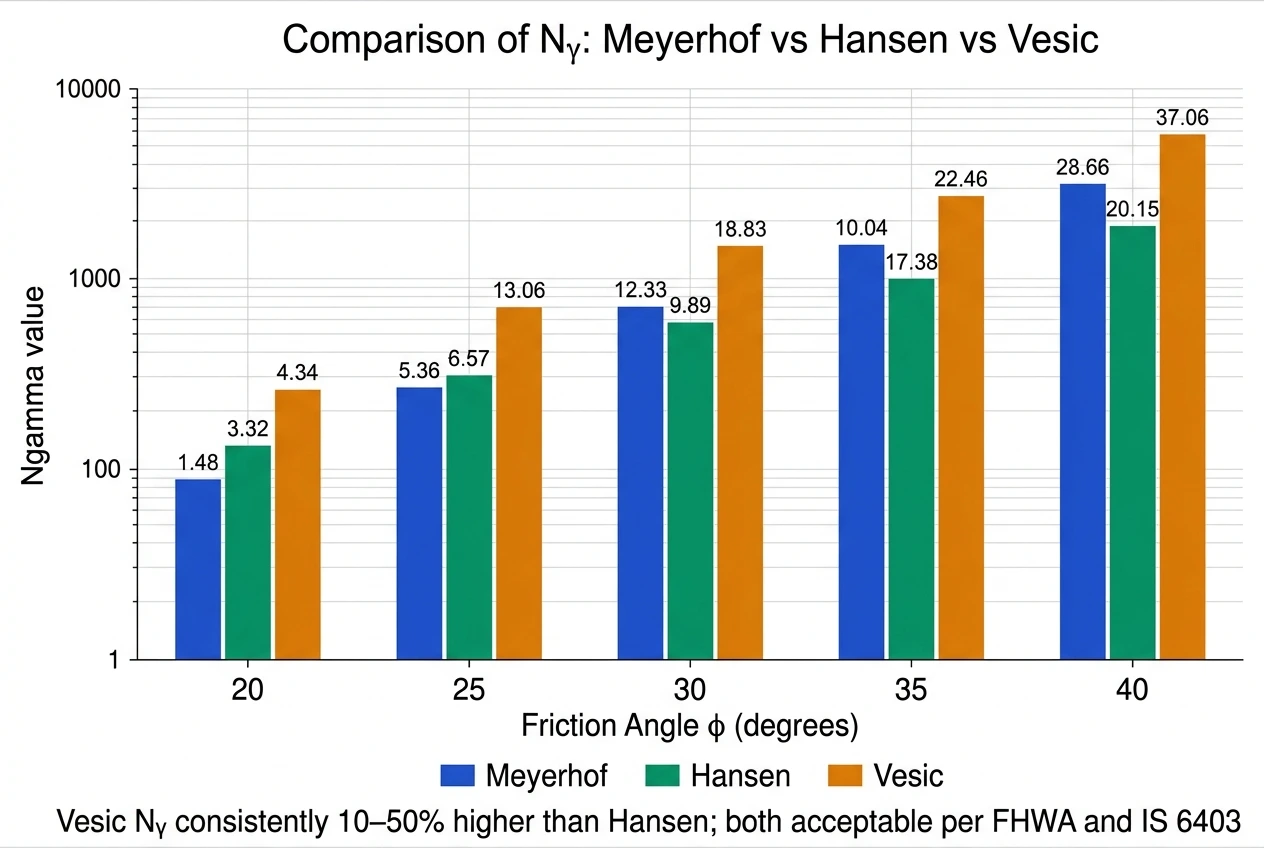
Chart 1 — Nc, Nq, Nγ vs. Friction Angle φ (log scale)
Comparison of all bearing capacity factors on a logarithmic scale. Note the rapid exponential growth above φ = 30° and the divergence between Vesic, Meyerhof, and Hansen Nγ expressions.
Chart 2 — qu vs. φ for Different GWT Positions (2.0 m square footing, Df = 1.5 m)
Meyerhof method with shape and depth factors; c = 0, γ = 19 kN/m³, γ' = 9.5 kN/m³. Shows how GWT position dramatically reduces qu — up to 55% in extreme cases.
Chart 3 — Meyerhof Allowable Bearing Pressure from SPT vs. Footing Width (Sand, 25 mm settlement)
Direct preliminary design chart. Allowable pressure decreases with increasing width beyond 1.2 m due to deeper influence zone. Use as first estimate only; confirm with formal analysis.
Chart 4 — Bearing Capacity Reduction Due to Load Inclination (Meyerhof iq, iγ)
Relative capacity (% of vertical-load capacity) vs. inclination angle α from vertical. Horizontal loads from wind, seismic, or lateral earth pressure can reduce capacity by 50–80%.

Ultimate Bearing Capacity Calculator (Meyerhof / Terzaghi)
Frequently Asked Questions
1. What is the difference between gross, net, safe, and allowable bearing capacity?
These four terms represent a sequence from theoretical maximum to practical design value. Gross ultimate bearing capacity (qu) is the total contact pressure at which shear failure occurs, calculated from Terzaghi, Meyerhof, Hansen, or Vesic equations. Net ultimate bearing capacity (qnu) subtracts the pre-existing overburden stress (gamma x Df), representing only the additional stress beyond what already existed. Safe bearing capacity (qs) divides qu by a factor of safety (2.5 to 3.0) against shear failure. Allowable bearing pressure (qa) is the final design value: the smaller of the net safe bearing capacity plus overburden (shear criterion) and the contact pressure that limits settlement to permissible values. For most foundations on clay or loose-medium sand, settlement governs and qa is the settlement-limited pressure.
2. What are Nc, Nq, and Ngamma in bearing capacity equations?
Nc, Nq, and Ngamma are dimensionless bearing capacity factors representing contributions of soil cohesion, overburden pressure, and soil self-weight. They are purely functions of friction angle phi. Nq represents surcharge resistance; it equals 1.0 for phi = 0. Nc represents cohesive resistance; its exact value for phi = 0 is 5.14 (pi + 2, Prandtl 1920). Ngamma represents resistance from soil self-weight below the footing; it is 0 for phi = 0. All three increase rapidly with phi: at phi = 30 degrees, Nq is approximately 18, Nc approximately 30, and Ngamma approximately 15 to 22 depending on the source. The exponential sensitivity to phi means accurate determination of friction angle is the most critical input.
3. Why does the groundwater table reduce bearing capacity and by how much?
Bearing capacity depends on effective stress. Below the groundwater table, effective unit weight drops from approximately 18-20 kN/m3 to approximately 8-11 kN/m3 (roughly halved). This affects two terms: the overburden term (q = gamma x Df) and the soil self-weight term (0.5 x gamma x B x Ngamma). For typical medium-dense sand, raising GWT from deep below the footing to the footing base level reduces ultimate bearing capacity by approximately 30-50 percent. A further rise to ground surface can cause reduction up to 55 percent. Three correction cases apply based on GWT position relative to Df and depth B below the footing base.
4. What factor of safety is appropriate for bearing capacity design?
IS 6403 recommends FoS = 2.5 to 3.0 applied to the net ultimate bearing capacity. The choice depends on: quality of soil investigation; soil variability; structure importance (critical structures use 3.0); construction quality control; and load reliability. AASHTO LRFD uses resistance factors (phi = 0.45 to 0.50), equivalent to FoS approximately 2.0 to 2.5. Eurocode 7 uses partial factors on material properties rather than a single FoS. Important: the FoS addresses shear failure only; settlement must be checked independently.
5. What is the Terzaghi formula for strip, square, circular, and rectangular footings?
Terzaghi (1943) gave separate equations for each shape. Strip: qu = c x Nc + q x Nq + 0.5 x gamma x B x Ngamma. Square: qu = 1.3 x c x Nc + q x Nq + 0.4 x gamma x B x Ngamma. Circular (diameter B): qu = 1.3 x c x Nc + q x Nq + 0.3 x gamma x B x Ngamma. Rectangular: qu = (1 + 0.3B/L) x c x Nc + q x Nq + (1 - 0.2B/L) x 0.5 x gamma x B x Ngamma. Meyerhof, Hansen, and Vesic later provided analytical shape factors that are more rigorous and are universally preferred for current design.
6. When should Meyerhof or Hansen be used instead of Terzaghi?
Terzaghi is adequate only for simple cases: shallow strip, square, or circular footings with vertical central load on level ground. Meyerhof, Hansen, or Vesic must be used whenever: the load is inclined (horizontal component from wind, seismic, lateral earth pressure); the footing is deeply embedded (Df/B greater than 1); the footing base is tilted (Hansen base inclination factors); the ground surface is sloped (Hansen ground inclination factors); the load is eccentric; or a rigorous shape factor formulation is needed. In general professional practice, Meyerhof or Hansen is always preferred over Terzaghi.
7. How does foundation depth Df affect bearing capacity?
Increasing Df improves bearing capacity through two mechanisms. First, it increases the overburden term q = gamma x Df, which multiplies with Nq; for sandy soils with large Nq this effect is substantial. Second, depth factors dc, dq, dgamma (all greater than 1.0 in Meyerhof and Hansen) account for the additional confinement and shearing resistance of the soil above the footing level. For purely cohesive clay (phi = 0), only dc contributes (dc = 1 + 0.4 x Df/B in Hansen), giving a modest increase. Practical minimum foundation depths per IS 1080: 0.5 to 1.0 m below any soft topsoil or fill.
8. What is the difference between general shear, local shear, and punching shear failure?
General shear failure occurs in dense or stiff soils (Dr greater than 67%, SPT N greater than 30). A well-defined continuous shear surface extends to the ground surface with pronounced heaving on both sides. The load-settlement curve shows a clear peak followed by sudden collapse. Local shear failure occurs in medium-density soils (Dr 35-67%, SPT N = 10-30). The failure zone does not reach the ground surface. Settlement is large before collapse and the curve has no sharp peak. Use Terzaghi with reduced parameters: c* = 0.67c and phi* = arctan(0.67tan phi). Punching shear failure occurs in very loose or soft soils (Dr less than 35%, SPT N less than 10). The footing punches straight down with no surface heave; continuous settlement without a distinct failure load.
9. How is bearing capacity estimated from SPT N-values?
SPT N-values are first corrected to N60 (standardising to 60 percent hammer energy) accounting for hammer type, borehole diameter, rod length, and sampler liner. Then corrected to (N1)60 (normalised to 100 kPa reference overburden) using CN = sqrt(100/sigma_v prime) limited to 2.0. Friction angle estimated from Peck correlations: phi from 25-28 degrees for N60 = 2-4, up to 38-43 degrees for N60 = 31-50. Undrained cohesion of clay: cu = 6 x N60 kPa (Terzaghi and Peck). Meyerhof (1956) direct allowable BC for sand: qa = N60/0.05 kPa for B less than 1.2 m; qa = N60/0.08 x ((B+0.3)/B) squared for B greater than 1.2 m, both for 25 mm settlement.
10. What is the effective width method for eccentric loading?
When the resultant vertical force does not pass through the centroid, Meyerhof effective width method replaces actual dimensions B and L with reduced effective dimensions: B prime = B minus 2eB and L prime = L minus 2eL, where eB = moment about B-axis divided by vertical load. Bearing capacity is computed using B prime and L prime for all terms including shape and depth factors. Total load capacity = qa x B prime x L prime. The eccentricity limit e less than or equal to B/6 ensures the resultant stays within the middle third and contact pressure remains compressive throughout.
11. What are the permissible settlements for shallow foundations per IS 1904?
IS 1904:1986 specifies: for isolated footings: sand and hard clay 25 mm total, 18 mm differential; soft clay 40 mm total (up to 65 mm), 25 mm differential. For raft foundations: sand 50 mm total, 25 mm differential; clay 65-100 mm total, 40-65 mm differential. The angular distortion should not exceed 1/500 for frame buildings. Differential settlement is more damaging than total settlement because it induces bending moments and cracking in structural elements.
12. What is the drained versus undrained analysis for bearing capacity?
Drained analysis uses effective strength parameters c prime and phi prime from CD or CU triaxial tests and represents long-term conditions. Undrained analysis uses total stress parameters cu and phi_u = 0 from UU triaxial or vane shear tests and represents the critical short-term condition in saturated clay immediately after rapid loading. For saturated clay, both must be checked; the more critical governs. For normally consolidated soft clay, undrained strength is typically lower and governs short-term design. For sandy soils, drainage is so rapid that the drained analysis always applies.
13. How does foundation shape (square, circular, strip) affect bearing capacity?
Shape affects bearing capacity through shape factors sc, sq, and sgamma. For the cohesion term (Nc), a square or circular footing has a higher factor than a strip: Terzaghi gives sc = 1.3 for square/circular vs 1.0 for strip. For the self-weight term (Ngamma), Hansen gives sgamma = 1 - 0.4 x B/L = 0.6 for square, reflecting 3D geometry. For purely cohesionless soil (c = 0) with phi greater than 0, a square footing typically has 20-30 percent higher qu per unit area than a strip footing of the same width, due to depth factor and shape factor advantages in the Nq term.
14. What is the relationship between SPT N-value and soil friction angle?
Several empirical correlations relate SPT N60 to drained friction angle phi prime for sands. Peck, Hanson and Thornburn (1974): N60 = 0-4 corresponds to phi = 25-28 degrees; 5-10: 28-30 degrees; 11-30: 30-36 degrees; 31-50: 36-41 degrees; over 50: over 41 degrees. Schmertmann (1975): phi prime = 27.1 + 0.3 x (N1)60 minus 0.00054 x (N1)60 squared. Hatanaka and Uchida (1996): phi prime = sqrt(20 x (N1)60) + 20 degrees. These correlations are approximate; for important projects, supplement SPT with laboratory tests.
15. What are the Terzaghi bearing capacity factors for phi = 0 (saturated clay, undrained)?
For phi = 0 (saturated clay, undrained analysis): Nc = 5.7 (Terzaghi original; Prandtl exact = 5.14), Nq = 1.0, and Ngamma = 0. The Nq = 1 term means the overburden term exactly cancels in the net bearing capacity calculation. The Ngamma = 0 term means soil self-weight below the footing contributes nothing. The entire net ultimate bearing capacity is therefore: qnu = Nc x cu = 5.14 x cu (strip, Prandtl) or 5.7 x cu (Terzaghi). For a square footing: qnu = 1.3 x 5.14 x cu = 6.68 x cu. This simplicity makes the phi = 0 analysis very practical for preliminary design on saturated clays.
16. What are the Meyerhof bearing capacity factors for phi = 36 degrees?
At phi = 36 degrees using the Meyerhof/Prandtl expressions: Nq = e^(pi x tan36) x tan^2(63) = approximately 39.15; Nc = (Nq minus 1) x cot36 = 38.15 x 1.376 = approximately 52.49; Ngamma (Meyerhof) = (Nq minus 1) x tan(50.4 degrees) = approximately 46.40; Ngamma (Hansen) = 1.5 x (Nq minus 1) x tan36 = approximately 41.59; Ngamma (Vesic) = 2 x (Nq plus 1) x tan36 = approximately 58.36. These values apply to very dense sands and compacted gravels. The large Nq of approximately 39 means even a modest Df of 1.5 m in dense sand contributes approximately 1,110 kPa to qu from the overburden term alone.
17. What is the Meyerhof shape factor formula sq = 1 + 0.1 B/L and the Hansen sgamma = 1 minus 0.4 B/L?
Meyerhof shape factors for phi greater than 10 degrees: sc = 1 + 0.2 x Nphi x (B/L); sq = 1 + 0.1 x Nphi x (B/L); sgamma = 1 + 0.1 x Nphi x (B/L); where Nphi = tan^2(45 + phi/2). For square at phi = 30 degrees (Nphi = 3.0): sq = 1.30, sgamma = 1.30. Hansen shape factors: sc = 1 + (Nq/Nc)(B/L); sq = 1 + (B/L)tan phi; sgamma = 1 minus 0.4(B/L). For square at phi = 30 degrees: sq = 1 + tan30 = 1.577; sgamma = 1 minus 0.4 = 0.60. The Hansen sgamma = 0.60 for square footings is significantly lower than Meyerhof s 1.30, reflecting different treatments of the 3D self-weight contribution. Meyerhof is more common in Indian textbooks; Hansen is standard in Eurocode 7.
18. What is the Meyerhof depth factor dq = 1 + 0.1 Df/B formula and how does it work?
The Meyerhof depth factor dq = 1 + 0.1 x k x sqrt(Nphi) for phi greater than 10 degrees, where k = Df/B. This accounts for the shear resistance of the soil above the footing base along the failure surface. For phi = 0, dq = 1.0. For phi = 30 degrees, sqrt(Nphi) = sqrt(3.0) = 1.732, so dq = 1 + 0.1 x (Df/B) x 1.732. For typical Df/B = 0.75: dq = 1.130, meaning a 13 percent increase in the Nq term from properly accounting for footing depth. Hansen depth factors are more conservative for Df/B less than 1 and more accurate for Df/B greater than 1, where Hansen uses arctan(Df/B) in radians instead of the ratio directly.
19. What is the Eurocode 7 Annex D undrained bearing capacity formula for square foundations?
For a square foundation on saturated clay under undrained conditions (phi_u = 0), Eurocode 7 Annex D gives: Rd/Af = (pi + 2) x cu x sc x dc + q, where pi + 2 = 5.14 (Prandtl exact). For a square footing with B = L: sc (Hansen) = 1 + (Nq/Nc)(B/L) = 1 + (1/5.14) x 1 = 1.195. The depth factor dc = 1 + 0.4 x arctan(Df/B) in radians. For Df/B = 0.5: dc = 1 + 0.4 x arctan(0.5) = 1.185. So qnu = 5.14 x 1.195 x 1.185 x cu = approximately 7.28 x cu. The simplified version (1 + 0.2 x B/L) x 5.14 = 1.2 x 5.14 = 6.17 x cu for shape factor only. This formula also appears in the formula (1 + 0.2 B/L) x 5.14 x cu that is sometimes written as (1+0.2(B/L)) x 5.14 x cu in examination notation.
20. What is the typical allowable bearing capacity of loose sandy soil in kPa?
The typical allowable bearing capacity of loose sandy soil is 50-100 kPa for a 25 mm settlement criterion, corresponding to SPT N60 values of approximately 5-10. The Meyerhof (1956) formula gives: for a 2.0 m wide footing with N60 = 8: qa = 8/0.08 x ((2.0+0.3)/2.0) squared = 100 x 1.32 = 132 kPa. IS 6403 Table 1 gives a presumptive allowable bearing capacity of 100 kPa for loose sand as a conservative preliminary value. From formal Meyerhof analysis at phi = 28 degrees with c = 0, B = 2.0 m, Df = 1.5 m, the allowable bearing pressure from shear failure (Fs = 3.0) is approximately 130-180 kPa, but settlement typically governs at 75-100 kPa for loose sand. BS 8004 historical presumptive value was also approximately 100 kPa for loose sand.
21. What is the typical allowable bearing capacity of firm clay in kPa?
Firm clay is defined by undrained shear strength cu approximately 50-75 kPa (SPT N60 approximately 7-11 in clay). Net ultimate bearing capacity for a strip footing: qnu = 5.14 x cu = 257 to 386 kPa. Applying Fs = 3.0: net safe BC = 86 to 129 kPa. Adding overburden (gamma x Df = 18 x 1.0 = 18 kPa): qa approximately 104 to 147 kPa. For a square footing with shape and depth factors this increases by about 20-30 percent. IS 6403 Table 1 gives a presumptive value of 100-200 kPa for medium stiff clay. BS 8004 (1986) quoted 100-200 kPa for firm to stiff clay. In practice 75-150 kPa is used accounting for the IS 1904 settlement criterion of 40 mm maximum for isolated footings on clay.
22. What is the soil bearing capacity symbol and standard notation?
In standard geotechnical notation: qu or qult = gross ultimate bearing capacity (kPa). qnu or qnet,ult = net ultimate bearing capacity = qu minus gamma x Df. qs or qsafe = safe bearing capacity = qu divided by Fs. qns = net safe bearing capacity = qnu divided by Fs. qa or qall or qallow = allowable bearing pressure, the final design value. qnet = net contact pressure from the structure. In IS 6403 these are specifically designated: qu (gross ultimate), qnet,ult (net ultimate), qs,gross (gross safe), qs,net (net safe), qa (allowable). In AASHTO LRFD the nominal bearing resistance qn replaces qu, and the factored resistance phi x qn is compared to the factored applied stress. In Eurocode 7 the design bearing resistance Rd/Af (kPa) is compared to the design bearing pressure sigma_v,d.
23. What is the soil bearing capacity chart showing typical values by soil type?
A soil bearing capacity chart organises allowable bearing pressures by soil type for preliminary design. Typical allowable gross bearing pressures (Fs = 3.0): Massive crystalline igneous rock 3,000-10,000 kPa; foliated metamorphic rock 1,500-3,000 kPa; weathered rock 300-800 kPa; compact well-graded gravel 600-900 kPa; loose gravel 200-400 kPa; dense coarse sand (N greater than 30) 300-500 kPa; medium dense sand (N = 15-30) 150-300 kPa; loose sand (N less than 10) 50-100 kPa; hard clay (cu greater than 200 kPa) 300-500 kPa; very stiff clay 150-300 kPa; stiff clay 100-150 kPa; firm clay 50-100 kPa; soft clay 25-50 kPa (settlement usually governs). These values are from IS 6403 Table 1, BS 8004:1986, and NAVFAC DM-7.02. Formal analysis is always required for final design.
24. What are the Terzaghi bearing capacity factors for phi = 32 degrees?
At phi = 32 degrees using the Meyerhof/Prandtl expressions (now universally standard): Nq = e^(pi x tan32) x tan^2(61) = approximately 23.18; Nc = (23.18 minus 1) x cot32 = 22.18 x 1.600 = approximately 35.49; Ngamma (Meyerhof) = (23.18 minus 1) x tan(44.8 degrees) = approximately 22.02; Ngamma (Hansen) = 1.5 x 22.18 x tan32 = approximately 20.79; Ngamma (Vesic) = 2 x (23.18 + 1) x tan32 = approximately 30.22. For local shear at phi = 32 degrees: phi* = arctan(2/3 x tan32) = arctan(0.4166) = 22.6 degrees; use the bearing capacity factors at 22.6 degrees.
25. What are the Terzaghi bearing capacity factors for phi = 35 degrees?
At phi = 35 degrees using Meyerhof/Prandtl expressions: Nq = e^(pi x tan35) x tan^2(62.5) = approximately 33.30; Nc = (33.30 minus 1) x cot35 = 32.30 x 1.428 = approximately 46.12; Ngamma (Meyerhof) = (33.30 minus 1) x tan(49 degrees) = 32.30 x 1.1504 = approximately 37.16; Ngamma (Hansen) = 1.5 x 32.30 x tan35 = approximately 33.93; Ngamma (Vesic) = 2 x (33.30 + 1) x tan35 = approximately 48.05. Note: Terzaghi s original tabulated values at phi = 35 degrees were: Nc = 57.75, Nq = 33.30, Ngamma = 34.00, which differ because Terzaghi used a slightly different Nq formula. For IS 6403 practice in India, Meyerhof/Hansen values are used.
References & Official Standards
- Terzaghi, K. (1943). Theoretical Soil Mechanics. John Wiley & Sons, New York.
- Meyerhof, G.G. (1951). The ultimate bearing capacity of foundations. Géotechnique, 2(4), 301–332.
- Meyerhof, G.G. (1963). Some recent research on the bearing capacity of foundations. Canadian Geotechnical Journal, 1(1), 16–26.
- Hansen, J.B. (1970). A Revised and Extended Formula for Bearing Capacity. Danish Geotechnical Institute Bulletin No. 28, Copenhagen.
- Vesic, A.S. (1973). Analysis of ultimate loads of shallow foundations. Journal of the Soil Mechanics and Foundations Division, ASCE, 99(1), 45–73.
- Vesic, A.S. (1975). Bearing capacity of shallow foundations. In H.F. Winterkorn & H.-Y. Fang (Eds.), Foundation Engineering Handbook (Ch. 3). Van Nostrand Reinhold, New York.
- Bureau of Indian Standards. (1981). IS 6403: Code of Practice for Determination of Bearing Capacity of Shallow Foundations. BIS, New Delhi. www.bis.gov.in
- Bureau of Indian Standards. (1986). IS 1904: Code of Practice for Design and Construction of Foundations in Soils — General Requirements. BIS, New Delhi.
- Bureau of Indian Standards. (2002). IS 2131: Method for Standard Penetration Test for Soils. BIS, New Delhi.
- Bureau of Indian Standards. (1992). IS 1888: Method of Load Test on Soils. BIS, New Delhi.
- European Committee for Standardization. (2004). EN 1997-1: Eurocode 7 — Geotechnical Design, Part 1: General Rules. CEN, Brussels. Annex D: Sample procedures to determine bearing resistance from analytical calculations.
- Bowles, J.E. (1996). Foundation Analysis and Design (5th ed.). McGraw-Hill, New York.
- Das, B.M. (2021). Principles of Foundation Engineering (9th ed.). Cengage Learning.
- Federal Highway Administration. (2006). FHWA NHI-06-089: Shallow Foundations — Reference Manual. US Department of Transportation. www.fhwa.dot.gov
- Robertson, P.K. & Campanella, R.G. (1983). Interpretation of cone penetration tests. Part I: Sand. Canadian Geotechnical Journal, 20(4), 718–733.
- Skempton, A.W. (1986). Standard penetration test procedures and the effects in sands of overburden pressure, relative density, particle size, ageing and overconsolidation. Géotechnique, 36(3), 425–447.
- Meyerhof, G.G. & Hanna, A.M. (1978). Ultimate bearing capacity of foundations on layered soils under inclined load. Canadian Geotechnical Journal, 15(4), 565–572.
- AASHTO. (2020). AASHTO LRFD Bridge Design Specifications (9th ed.). American Association of State Highway and Transportation Officials, Washington, D.C.
Explore More Foundation Engineering Resources
Pile foundations, retaining walls, soil stabilization, sieve analysis, and more in our complete library.